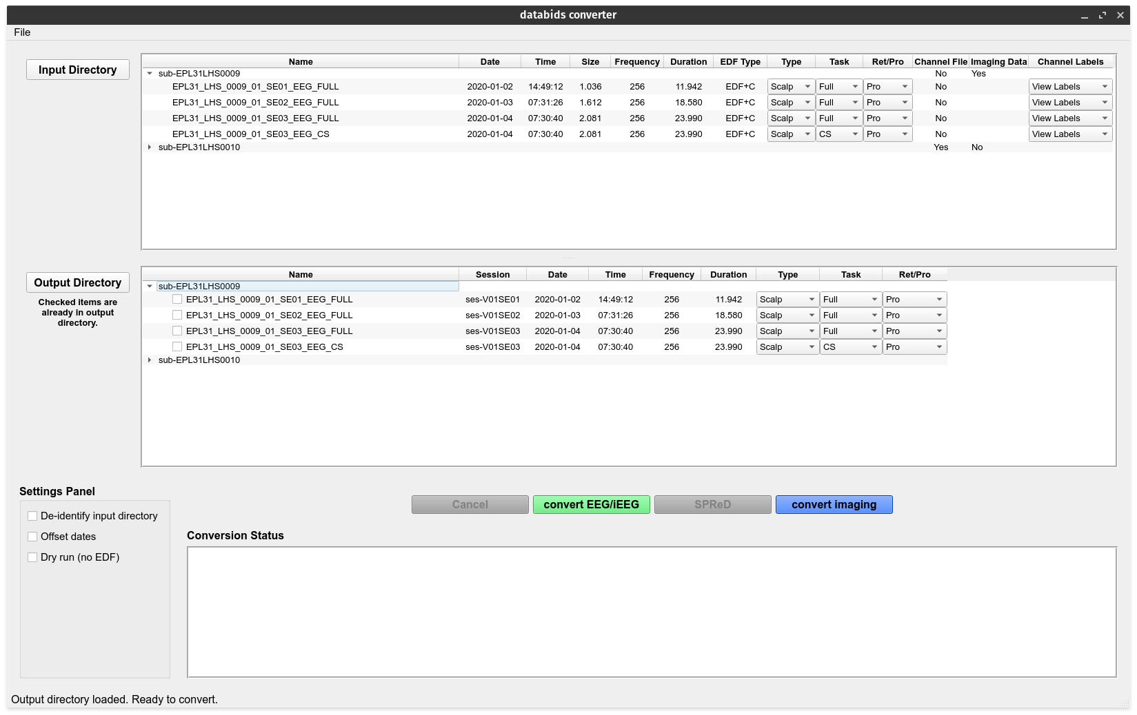
Currently, data2bids will convert EDF/EDF+ and DICOM file formats into a Brain Imaging Data Structure compliant format.

European Data Format (EDF)
The European Data Format (EDF) is a simple and flexible format for exchange and storage of multichannel biological and physical signals. It was developed by a few European medical engineers who first met at the 1987 international Sleep Congress in Copenhagen. In March 1990, they agreed upon a very simple file format to exchange their sleep recordings. This format became known as the European Data Format.
An extension of EDF, named EDF+, was developed in 2002 and is largely compatible to EDF. However, the EDF+ format provides a few advantages: the files can contain interrupted recordings, annotations can be stored within the file along with stimuli/events. Medical type recordings often contain annotations about patient events, stimulation responses and are often discontinuous as the patient may require breaks during recording time. EDF+ allows for these medical type recordings to be stored much easier.
The full specifications can be found on the EDF website. The site also supports users and developers by offering free downloads of files and software, a list of EDF(+) compatible companies and further contact possibilities.
EDF File Structure
EDF/EDF+ files consist of a header (ascii) that describes the contents of the file and the experimental settings. The data (int16) are stored after the header.
The Header
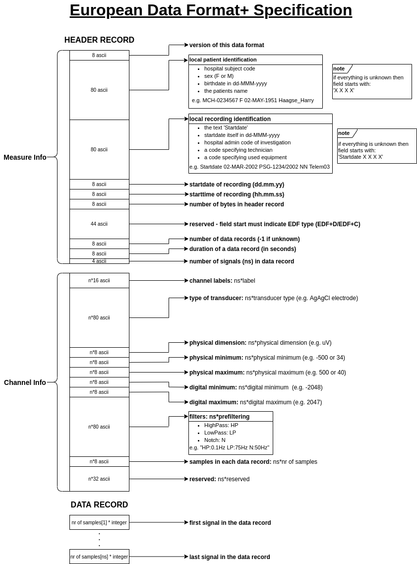
The EDF/EDF+ header is split into two parts: measurement info and channel info. The measurement info contains general information about the recording while the channel info contains specific information about each channel used to record. Thus, the length of the full header (the ‘header record’) equals:
measurement info (256) + channel info (number of channels * 256)
The header record is ascii only, and contains the following fields:
Measurement Info
The first 256 bytes in an EDF/EDF+ file is allocated to the measurement info (i.e. patient info, date and time of data acquisition, etc.).
| Field | Size | Position | Notes |
|---|---|---|---|
| version | 8 | 0 | version is always 0 |
| patient id | 80 | 8 | Code Sex DOB Name1 |
| recording id | 80 | 88 | Startdate start_date ExpID InvestigID Equipment2 |
| startdate | 8 | 168 | dd.mm.yy |
| starttime | 8 | 176 | hh.mm.ss |
| number of bytes in header | 8 | 184 | |
| reserved | 44 | 192 |
|
| number of data records | 8 | 236 | nr |
| duration of data record | 8 | 244 | in seconds |
| number of signals | 4 | 252 | ns |
total |
256 |
1 patient id
- Code: hospital subject code
- Sex: F or M
- DOB: birthdate in dd-MMM-yyyy
- Name: the patients name
e.g. MCH-0234567 F 02-MAY-1951 Haagse_Harry
2 recording id
- Startdate: the text
Startdate - start_date: start date itself in dd-MMM-yyyy
- InvestigID: a code specifying the technition/clinician
- Equipment: a code specifying used equipment
e.g. Startdate 02-MAR-2002 PSG-1234/2002 NN Telem03
Channel Info
The channel info record is 256 bytes and each channel has its own channel info record. For instance, if 10 channels are used to record then there would be 10 * channel info records within the EDF/EDF+ header. For each channel, the following information is stored:
| Field | Size | Position | Notes |
|---|---|---|---|
| label | 16 | 0 | |
| transducer | 80 | 16 | transducer type (i.e AgAgCl electrode) |
| physical dim | 8 | 96 | physical dimension of channel data (i.e. μV) |
| physical min | 8 | 104 | |
| physical max | 8 | 112 | |
| digital min | 8 | 120 | 1 |
| digital max | 8 | 128 | 1 |
| prefiltering | 80 | 136 | high-pass, low-pass and notch filters2 |
| number of samples | 8 | 216 | |
| reserved | 32 | 224 | |
total |
256 |
1 digital min/max
- digital range must be somewhere between -32768 and 32767 (because data samples are 16-bit signed integers)
2 prefiltering
- HighPass: HP
- LowPass: LP
- Notch: N
e.g. HP:0.1Hz LP:75Hz N:60Hz
After the channel info header blocks there are 256 bytes for each channel acquired.
Note
each field in the channel info record holds the values for all channels (rather than the header storing one full channel record, then a second full channel record, etc). That is, if e.g. two channels are acquired, then there will be two consecutive label fields (16 + 16 bytes), then two consecutive transducer fields (80 + 80 bytes), then two physical dim fields (8 + 8 bytes), etc.
Data Record
Data records follow after the header record. Here, data samples (of type int16) are stored in blocks ('data record'). Each block contains the samples acquired during a period of time specified in the header as duration of data record, and the total number of blocks in the file are number of data records.
Note
Note that EDF allows the acquisition of signals at different sampling rates; the number of samples per signal in each data block is in the signal header as number of samples in data record.
For example, two signals signal_A and signal_B are acquired at 100 Hz and 5 Hz respectively. The data are saved every 20 seconds (duration of data record = 20). Thus, one block of data (a data record)will consist of 2000 samples (number of samples in data record = 100 Hz * 20 secs = 2000) from signal_A followed by 100 samples (number of samples in data record = 5 Hz * 20 seconds = 100) from signal_B. If the header indicates that there are 70 such blocks (number of data records = 70), then the total duration of the recording would be 70 x 20 = 1400 seconds (number of data records *
duration of data record).
EDF File Structure Diagram
